
Various defects can arise during the injection molding process. This article categorizes 28 common, frequently occurring injection molding defects into six major groups. Each entry describes visible defects, root causes and process fixes, flags mold and material checkpoints to speed up troubleshooting, and you can check the Meusburger injection molding defection analysis for extra technical context.
Surface Appearance Injection Molding Defects
This category primarily addresses issues related to the texture, marks, color, and appearance of a product’s surface.
Sink Marks
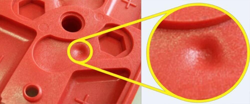
- Appearance:Local surface depressions mostly on thick walls, bosses and rib backs, with uneven gloss and a sunken feel.
- Causes:Heavy shrinkage in thick sections, insufficient packing pressure or short hold time, high melt and mold temperature, small earlyfreezing gates, sharp wall thickness changes and oversize ribs.
- Solutions:Raise packing pressure and hold time, moderately lower melt and mold temperatures.
- Mold:Thin ribs and remove abrupt wall-thickness transitions.
- Material:Lowshrinkage ABS, PC and PC/ABS are preferred. Glass filled grades control shrinkage for high strength needs. Avoid PP, PE and POM; their high shrinkage brings high risk on thick or cosmetic surfaces.
- Tip:PP, PE and POM easily produce sink marks, so use them carefully on thick sections and visible exterior surfaces.
Weld Lines
- Appearance:Dark thin lines with uneven gloss and slight texture form where two melt fronts meet, and these weak spots crack easily under load.
- Causes:Cooling and trapped air before merging lead to poor fusion. For glass filled grades, misaligned fibers make weld lines extremely brittle.
- Solutions:Raise melt and mold temperature, speed up injection, rework gate layout and improve venting.
- Mold:Reduce holes and pillars that split the melt flow.
- Material:ABS and PC/ABS with good flow are preferred, while modified glassfilled grades boost weld strength for high-load parts; avoid POM, PP, PE and standard unmodified glass filled resins.
- Tip:Glassfilled parts suffer severe weld line weakness, so keep load bearing areas away from melt convergence lines.
Flow Marks
- Appearance:Wavy snakeskin patterns appear near gates, with uneven gloss and subtle surface irregularities.
- Causes;Slow injection cools the melt front early. Restrictive gates, narrow runners and poorly dispersed additives also disrupt flow.
- Solutions:Raise melt and mold temperatures, boost injection speed and tune multistage injection settings.
- Mold:Widen gates and runners for smoother flow.
- Material:Avoid high viscosity unmodified PBT.High flow ABS and PC/ABS provide consistent filling.
- Tip:Flow marks are cosmetic issues; adjust speed and gate design first.
Jetting
- Appearance:Snaking jet streaks start at gates with sharp boundaries.Severe jetting forms folded, poorly fused strands, hurting appearance and local strength. It differs from flow marks.
- Causes:High speed melt jets straight into empty cavity,low melt or mold temperature and gates positioned too far from mold walls with no buffer.
- Solutions:Reduce initial injection speed and moderately raise melt and mold temperature.
- Mold:Thicken gates, reposition gates toward mold walls,add baffles or overflow wells to stop direct jetting.
- Material:ABS and PC/ABS with moderate flow work best; highviscosity resins, prone to jetting should be avoided.
- Tip:Jetting is often mistaken for flow marks, yet it streaks start right at gates and carry sharper edges.
Silver streaks / Water marks
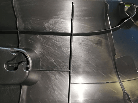
- Appearance:Air traps seldom occur in isolation, often triggering secondary defects such as burns, short shots, silver streaks and blisters.
- Causes:Fast moving melt pushes cavity air ahead before it can escape, much like trapped air in a sealed bottle. Poor gate layout, shallow or blocked vents, fast injection and enclosed dead zones all lead to air traps.
- Solutions:Slow injection speed, improve venting, reposition gates and remove enclosed dead spots.
- Mold:Add vents at melt flow ends and clear blocked vent slots.
- Material:Highviscosity PC and unmodified PBT easily trap air with their thick melt, unlike ABS and PC/ABS that deliver steady flow.
Delamination
- Appearance:Unlike weak weld lines,it means material peels apart.Part surface layers peel away,with separated interfaces visible on cross sections near gates or weld lines.
- Causes:Incompatible resins,low barreltemperature and material contamination.
- Solutions:Dry raw materials thoroughly, regulate regrind quality and limit mixed resin grades, while moderately raising melt and mold temperatures and maintaining steady injection speed.
- Mold::Purge the barrel to eliminate leftover crosscontaminated materials.
- Material:Stick to compatible ABS and PC/ABS. Never blend incompatible resins such as ABS with PP, which easily delaminate.
- Tip:Faint delamination can escape visual inspection, with bend or impact tests on samples used to reveal peeling.
Dimensional and Deformation Injection Molding Defects
Warpage
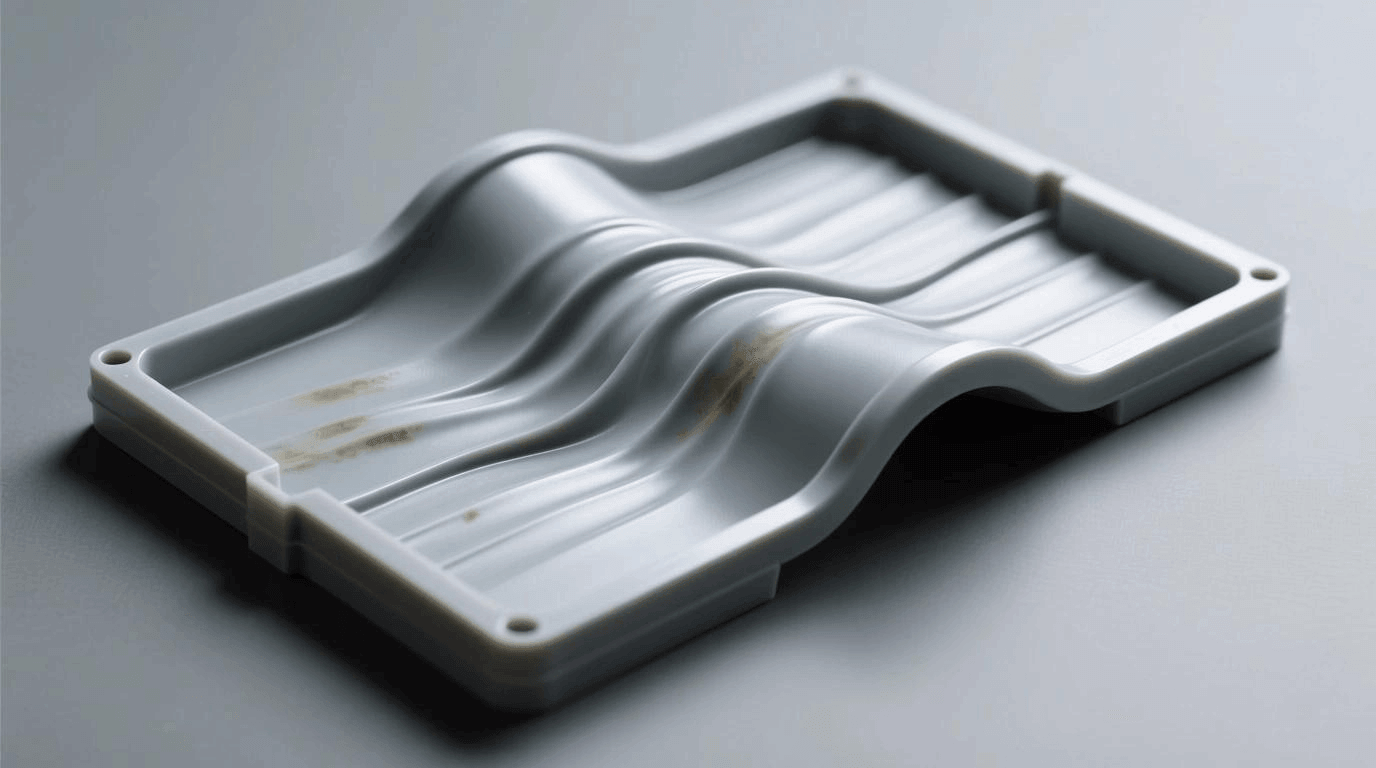
- Appearance:Parts bend, arch or twist after cooling and fail flatness specs. It commonly occurs on thin flat and asymmetric designs, different from localized sink marks.
- Causes:Unbalanced cooling, residual internal stress, uneven wall thickness and inconsistent packing.
- Solutions:You address warpage through balanced cooling, optimized packing, smooth wall transitions and adjusted gate placement..
- Mold:Revise cooling channels and redesign parts to reduce asymmetric geometry.
- Material:Lowshrink PC/ABS delivers stable shrinkage,while high crystalline PP, PE and glass filled grades carry warpage risks from shrinkage or fiber orientation.
- Tip:Conduct visual checks against fixtures for quick screening, with calipers or CMM sampling deployed to verify flatness for tight-tolerance requirements.
Shrinkage
- Appearance:The molded part shrinks overall and falls below drawing dimensions after cooling. This differs from sink marks, which are only local surface depressions.
- Causes:Polymer chains contract and volume reduces as melt cools, much like dough shrinking.High crystalline resins, thick walls, insufficient packing and high melt temperature worsen shrinkage.
- Solutions:You control dimensional deviation through pre-set mold shrinkage allowance, increased packing pressure and hold time, plus moderately reduced melt temperature.
- Mold:Optimize gate placement for consistent feeding and equalize wall thickness to minimize shrinkage variation.
- Material:PC/ABS and ABS offer low, consistent shrinkage, versus highly crystalline PP and PE with high shrinkage and unstable dimensions.
Dimensional Inaccuracy
- Appearance:Critical dimensions drift out of tolerance, alternating between oversize and undersize.Unlike uniform overall shrinkage, this defect means inconsistent part sizes within the same batch.
- Causes:Dimensional inconsistency arises from variable process parameters, unstable packing and temperature, worn molds, loose inserts, resin shrinkage drift between batches, uneven cooling and release deformation.
- Solutions:You stabilize dimensions by locking molding parameters, checking batch shrinkage, balancing cooling and standardizing demolding.
- Mold:Inspect and calibrate molds regularly, and secure loose inserts.
- Material:ABS and PC/ABS are preferred for consistent shrinkage and low batch variation. Highly crystalline PP and PE show shrinkage sensitive to temperature and pressure.
- Tip:You re-evaluate the supplier for repeated, hardto resolve out of tolerance problems, and roll out corrective actions with higher sampling frequency for isolated anomalies.
Ejector Marks
- Appearance:Indentations, bumps or circular rings form exactly at ejector pin locations, fixed to the pin layout. These differ from flow marks, which follow melt flow paths.
- Causes:Excessive ejection force, poor pin layout, worn uneven pin surfaces, premature ejection before full cooling and flash from loose pin clearance create this defect much like pushing into a soft undercooled cake and leaving dents.
- Solutions:Extend cooling time, distribute ejector pins evenly to spread force, reduce ejection speed and pressure, and increase pin contact area.
- Mold:Polish and level pin ends and adjust pin-to-hole clearance.
- Material:ABS and PC/ABS hold good rigidity after cooling, while soft TPE and flexible PP tend to develop noticeable pin marks.
Vacuum Voids
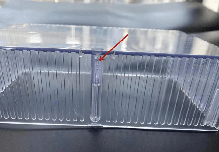
- Appearance:Vacuum voids hide inside thick sections and normally stay invisible externally, with smooth walled cavities showing when parts are cut open.
- Causes:Internal shrinkage continues without fresh melt feed, creating negative pressure that pulls vacuum cavities.
- Solutions:Extended packing time, higher packing pressure, gates positioned on thick sections and slower surface skin solidification help fix vacuum voids.
- Mold:Redesign parts to eliminate heavy stock and adjust cooling sequence.
- Material:PC/ABS and ABS bring stable shrinkage and lower void risk on thick walls, while highly crystalline PP and PE are prone to voids from heavy shrinkage.
Moisture Defects
- Appearance:Silver streaks, water marks and bubbles produce cloudy whitish surfaces, and severe instances develop voids with reduced part strength.
- CausesMoisture turns to steam in the hot barrel, like bubbles from wet baked dough. Poor drying, damp storage and heat induced hydrolysis trigger this issue.
- SolutionsDry resin fully before molding, use dehumidifying dryers for hygroscopic materials, control barrel heat and seal resin against re
- MoldKeep feed paths dry and cut resin residence time in the barrel.
- MaterialABS and PC/ABS feature low moisture absorption, while nylon and PET are highly hygroscopic and demand strict drying.
- TipVisual inspection catches surface flaws, while sectioning or NDT applies to critical parts.Even trace moisture causes defects; drying matters most.
Brittleness
- Appearance:Parts snap easily under light bending with flat fracture surfaces. Unlike stress cracks, brittleness means the material itself turns fragile.
- Causes:Thermal degradation, overdrying, high regrind content, fast cooling or low inherent toughness.
- Solutions:Stabilize barrel temperature, limit regrind, standardize drying and adjust cooling.
- Mold:Optimize cooling channels to prevent rapid quenching.
- Material:Select high-toughness PC/ABS rather than GPPS, which is inherently brittle.
- Tip:Test samples with bending or drop impact; lowtemperature checks uncover hidden brittleness risks.
Stress Cracking
- Appearance:Fine hairline cracks form at sharp corners,wall transitions and loaded assembly zones.Triggered by residual stress and chemicals, not direct mechanical force.
- Causes:Molded in residual stress, stress concentration, and chemical agents that weaken molecular bonds.
- Solutions:Add radii, smooth wall transitions, lower packing pressure, anneal parts and avoid incompatible chemicals.
- Mold:Remove sharp stress risers in part geometry.
- Material:Hightoughness PC/ABS is the better choice, as GPPS tends to crack when exposed to solvents.
- Tip:Visual inspection paired with solvent soak tests uncover hidden cracks, and samples get validated under assembly load.
Ejection and Demoding Injection Molding Defects
Sticking
- Appearance:Parts stick to the mold and resist release, leading to scuffs,whitening or tearing, and this defect differs from ejector pin marks.
- CausesInsufficient draft, over polished mold surface, poor release agent, high packing, insufficient cooling and improper mold temperature.
- SolutionsIncrease draft angle, adjust mold texture, apply release agent correctly, lower packing pressure and extend cooling.
- MoldPolish sticking prone areas
- MaterialABS and PC/ABS deliver clean release, yet high-tack TPE tends to stick.
- TipWatch for frequent sticking. It often leads to whitening and cracking; adjust mold and process first.
DragMarks
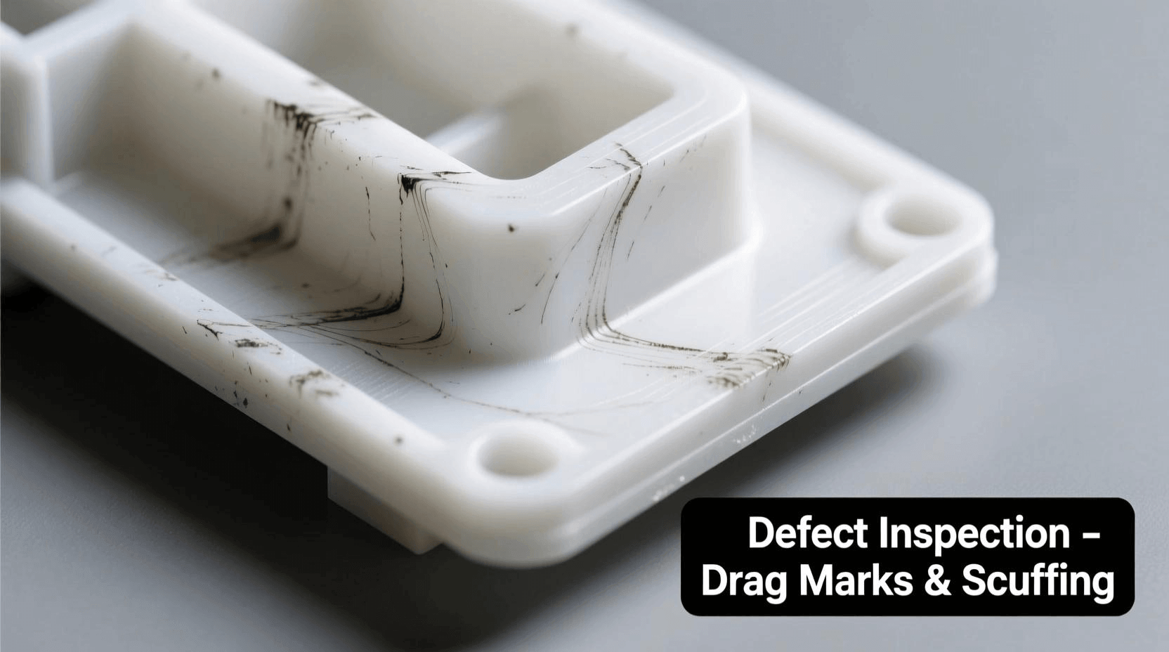
- Appearance:Linear scratches or whitish streaks form on side walls and raised features during ejection, often alongside sticking.
- Causes:Small draft angles, rough mold surfaces, burrs, and unbalanced ejection that create friction.
- Solutions:Add draft, polish mold surfaces and remove burrswith balanced ejection speed to reduce drag.
- Mold:Smooth side walls and sharp edges.
- Material:ABS and PC/ABS offer good scuff resistance. Soft TPE and flexible PP tend to whiten under friction.
- Tip:Check side walls and raised features for streaks. Drag marks often accompany sticking, so prioritize mold draft optimization.
Ejector Pin Deformation
- AppearanceBent or tilted ejector pins leave irregular, offset indentations on parts unlike clean, defined ejector pin marks.
- CausesThin pins, excessive ejection force, unbalanced pin loading and ejection before full cooling.
- SolutionsReduce ejection speed and force, extend cooling time, and distribute ejection load evenly.
- MoldYou fit thicker, stronger pins and align the ejector plate for synchronized movement.
- MaterialABS and PC/ABS are preferred for high rigidity after cooling. Avoid soft TPE and flexible PP, which pick up uneven marks easily.
- TipCheck whether marks shift from expected positions. Recurring deformation requires ejector assembly inspection.
Injection Molding Defects Troubleshooting Chart
|
Defect |
Main Cause |
Recommended Solution |
|
Sink Marks |
Uneven wall thickness, insufficient packing |
Optimize wall thickness and packing pressure |
|
Weld Lines |
Poor melt fusion, low temperature |
Increase melt temperature and optimize gate location |
|
Short Shots |
Insufficient injection pressure |
Adjust injection pressure and improve venting |
|
Flash |
Excessive injection pressure, poor mold clamping |
Check clamping force and mold condition |
|
Warpage |
Uneven cooling and shrinkage |
Balance cooling and optimize part design |
|
Silver Streaks |
Moisture in plastic resin |
Dry materials properly |
|
Burn Marks |
Trapped air and excessive heat |
Improve mold venting and adjust injection speed |
|
Sticking |
Insufficient draft angle, poor release |
Optimize draft angles and ejection system |
FAQ
1 What are the most common injection molding defects?
The most common injection molding defects include sink marks, warpage, flash, short shots, weld lines, burn marks, voids, and flow lines.
2 What causes most injection molding defects?
Most injection molding defects are caused by improper processing parameters, poor mold design, inconsistent material quality, and inadequate cooling.Factors such as incorrect injection pressure, melt temperature, cooling time, and mold venting can lead to defects like flash, sink marks,warpage and short shots.
3 Can injection molding defects be fixed by adjusting process parameters?
Some injection molding defects can be fixed by adjusting process parameters, while others need mold revisions or material replacement.
4 How can manufacturers reduce injection molding defects?
Manufacturers can cut injection molding defects by validating material drying, optimizing mold venting and cooling, stabilizing process parameters,and checking part design upfront.
Conclusion
If you have further questions about injection molding defects, feel free to reach out to Grandshine.We are ready to share guidance and support your project.


Related Posts
Quality Assurance & Quality Control | Definition-Difference-Methods-Process
what is the injection molding-part1
Some tips help you understand electric injection molding machines